Friday, September 21, 2012

A Comprehensive Discussion Over Topographic maps vs. topological maps


A topographic map is primarily concerned with the topographic description of a place, including (especially in the 20th century) the use of contour lines showing elevation. Terrain or relief can be shown in a variety of ways.


There are a few rules that topographic contours must obey, however, and once you understand these rules the map becomes an extremely useful and easy to use tool.

Every point on a contour line represents the exact same elevation. Contour lines on the edge of a map do not appear to close on themselves because they run into the edge of the map, but if you got the adjacent map you would find that, eventually, the contour will close on itself.

Contour lines can never cross one another. Each line represents a separate elevation, and you can’t have two different elevations at the same point. The only exception to this rule is if you have an overhanging cliff or cave where, if you drilled a hole straight down from the upper surface, you would intersect the earth’s surface at two elevations at the same X, Y coordinate.

In this relatively rare case, the contour line representing the lower elevation is dashed. The only time two contour lines may merge is if there is a vertical cliff.

Moving from one contour line to another always indicates a change in elevation. To determine if it is a positive (uphill) or negative (downhill) change you must look at the index contours on either side (see figure).

On a hill with a consistent slope, there are always four intermediate contours for every index contour. If there are more than four index contours it means that there has been a change of slope and one or more contour line has been duplicated. This is most common when going over the top of a hill or across a valley.

The closer contour lines are to one another, the steeper the slope is in the real world. If the contour lines are evenly spaced it is a constant slope, if they are not evenly spaced the slope changes.

A series of closed contours (the contours make a circle) represents a hill. If the closed contours are hatchured it indicates a closed depression (see figure).

Contour lines crossing a stream valley will form a "V" shape pointing in the uphill (and upstream) direction .

Various type of photographs used in aerial photogrammetry.


This is a continuation of previous post about various type of photographs used in aerial photogrammetry.
Vertical photo for aerial photogrammetry
A vertical photograph for aerial photogrammetry is taken with the camera pointed as straight down as possible Allowable tolerance is usually + 3° from the perpendicular (plumb) line to the camera axis. The result is coincident with the camera axis. A vertical photograph has the following characteristics:

(1)   The lens axis is perpendicular to the surface of the earth.
(2)   It covers a relatively small area.
(3)   The shape of the ground area covered on a single vertical photo closely approximates a square or rectangle.
(4)   Being a view from above, it gives an unfamiliar view of the ground.
(5)   Distance and directions may approach the accuracy of maps if taken over flat terrain.
(6)   Relief is not readily apparent.

Three terms need defining here; they are Principal Point, Nadir and Isocenter.  They are defined as follows:

 1. Principal Point - The principal point is the point where the perpendicular projected through the center of the lens intersects the photo image.

 2. Nadir - The Nadir is the point vertically beneath the camera center at the time of exposure.

 3. Isocenter - The point on the photo that falls on a line half- way between the principal point and the Nadir point. 


Low Oblique for aerial photogrammetry 

 This is a photograph for aerial photogrammetry taken with the camera inclined about 30° from the vertical. It is used to study an area before an attack, to substitute for a reconnaissance, to substitute for a map, or to supplement a map. A low oblique has the following characteristics:

(1)   It covers a relatively small area.
(2)   The ground area covered is a trapezoid, although the photo is square or rectangular.
(3)   The objects have a more familiar view, comparable to viewing from the top of a high hill or tall building.
(4)   No scale is applicable to the entire photograph, and distance cannot be measured. Parallel lines on the ground are not parallel on this photograph; therefore, direction (azimuth) cannot be measured.
(5)   Relief is discernible but distorted.
(6)   It does not show the horizon.


High Oblique for aerial photogrammetry

The high oblique for aerial photogrammetry is a photograph taken with the camera inclined about 60° from the vertical. It has a limited military application; it is used primarily in the making of aeronautical charts. However, it may be the only photography available. A high oblique has the following characteristics:

(1)   It covers a very large area (not all usable).
(2)   The ground area covered is a trapezoid, but the photograph is square or rectangular.
(3)   The view varies from the very familiar to unfamiliar, depending on the height at which the photograph is taken.
(4)   Distances and directions are not measured on this photograph for the same reasons that they are not measured on the low oblique.
(5)   Relief may be quite discernible but distorted as in any oblique view. The relief is not apparent in a high altitude, high oblique.
(6)   The horizon is always visible.

Trimetrogon for aerial photogrammetry 


This is an assemblage of three photographs taken at the same time, one vertical and two high obliques, in a direction at right angle to the line of flight. The obliques, taken at an angle of 60° from the vertical, side lap the vertical photography, producing composites from horizon to horizon.

Multiple Lens Photography for aerial photogrammetry : These are composite photographs taken with one camera having two or more lenses, or by two or more cameras. The photographs are combinations of two, four, or eight obliques around a vertical. The obliques are rectified to permit assembly as verticals on a common plane.

Convergent Photography for aerial photogrammetry: These are done with a single twin-lens, wide-angle camera, or with two single-lens, wide-angle cameras coupled rigidly in the same mount so that each camera axis converges when intentionally tilted a prescribed amount (usually 15 or 20°) from the vertical. Again, the cameras are exposed at the same time. For precision mapping, the optical axes of the cameras are parallel to the line of flight, and for reconnaissance photography, the camera axes are at high angles to the line of flight.

Panoramic for aerial photogrammetry: The development and increasing use of panoramic photography in aerial reconnaissance has resulted from the need to cover in greater detail more and more areas of the world.
(1)  To cover the large areas involved, and to resolve the desired ground detail, present-day reconnaissance systems must operate at extremely high-resolution levels. Unfortunately, high-resolution levels and wide-angular coverage are basically contradicting requirements.

(2)   A panoramic camera is a scanning type of camera that sweeps the terrain of interest from side to side across the direction of flight. This permits the panoramic camera to record a much wider area of ground than either frame or strip cameras. As in the case of the frame cameras, continuous cover is obtained by properly spaced exposures timed to give sufficient overlap between frames. Panoramic cameras are most advantageous for applications requiring the resolution of small ground detail from high altitudes.

A comprehensive discussion over various aerial cameras


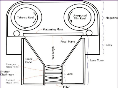
The various types of aerial cameras used in taking photographs is quite different than the ordinary camera as in case of aerial camera. 

aerial camera


Various types of aerial camears:

Single lens camera: A single-lens reflex (SLR) camera is a camera that uses a semi-automatic moving mirror system which permits the photographer to sometimes see exactly what will be captured by the film or digital imaging system, as opposed to pre-SLR cameras where the view through the viewfinder could be significantly different from what was captured on film.

Multi lens camera: The multi-lens camera is a unique piece of technology that follows the principles of lomography for capturing still images. Lomography encourages a light-hearted approach to photography and encompasses over-saturated colors in the images, blurring, and alternative film processing techniques.
Strip Camera:

Panoramic Camera: 
Digital Cameras:
 The use of digital cameras is slowly increasing in popularity, paralleling the popularity of digital cameras in the general public.

The CCD (charged coupled device) is the electronic component on which the light from the lens is focused.
 Digital pictures are made up of tiny "squares", each of a single color, called pixels. Each CCD has a maximum number of pixels that it uses to generate the image.
 Camera specifications will list the Max Resolution and the Minimum Resolution.

Some of the cameras used in aerial photography are:

-Zeiss RMK 15/23(digital camera)

23*23 cms picture format,6 inch focal length
-2fairchild kc-6A
23*23 cms picture format,6 inch focal length
Wild RC-10
 (having different focal  lengths;89,152,210,305 mm)
Hasselblad MK-70
Itek LfC (large format camera )

Aerial triangulation in 3D aerial photogrammetry


Aerial triangulation in 3D aerial photogrammetry is a mathematical process used to determine the position and orientation of each photograph at the moment of exposure. Aerial triangulation in 3D aerial photogrammetry solves for each photo’s exterior orientation parameters, which convey the information necessary to convert image measurements into ground coordinates, as well as determine image points that correspond to points on the ground.

aerial traingulation


- Aerial triangulation in 3D aerial photogrammetry is a critical step related to the project’s quality, and is at the heart of all photogrammetric processes.

- The computed result of Aerial Triangulation in 3D aerial photogrammetry gives the computed EO parameters (X, Y, Z, omega, phi, kappa) which is used to generate the highly accurate stereo model (3D) without any parallax which is further used for DTM generation, Orthophoto creation, Mapping purposes, Application of different projects like urban planning, Utility mapping etc. 

- Aerial Triangulation in photogrammetry is the first step to perform in the Photogrammetric Project. 

- Aerial triangulation has been a complex operation which includes planning the photo flight, establishing ground control points, taking and developing aerial photographs based on preset specifications, performing interior orientation, measuring and transferring all tie, check, and control points appearing on all photographs, and performing a least squares block adjustment.

- This process ultimately provides the exterior orientation parameters for all photographs and the three dimensional coordinates for all measured object points.

- Inner Orientation requires measurement of image coordinates of fiducial marks; this orientation is followed for the images taken with analog camera which is having fiducial marks. 

- The measurement of tie points could be done manually or automatically. 

- The automatic measurement of corresponding points for Relative Orientation is based on the image matching. 

- The measurements of control points are necessary for Absolute Orientation of photogrammetric model. 

- The knowledge about convenient choice of their position is important for good quality of the training process. 


- The automatic identification of control points is more difficult. At present there are two strategy lines in practical use, which can be pursued in digital aerial triangulation in 3D aerial photogrammetry. 

- The first strategy uses semi-automatic methods in which the human operator selects interactively one or several suitable tie-points in an image and gives the approximate location of its homologous points in the other images. Then the image point is transferred automatically by image matching.

- The second strategy, which is pursued here, goes one essential step further and attempts a fully automated procedure for selecting, transferring (matching) and measuring tie-points. 

- In this case not only the selection of tie-points is automatic but the approximations are obtained automatically too. The operator only has to give the initial approximations (block-configuration, forward- and side-overlap) and control the results. 

- The main specifications of aerial traingulation in 3D aerial photogrammetry is the system’s concept are automation and sub pixel accuracy.

What is Photographic Film in aerial photogrammetry


Various types of Films and Lenses are used in aerial photogrammetry. Here we have discussed a verious type of films and lenses used in aerial photogrammetry. Photographic film is a sheet of plastic (polyester, nitrocellulose or cellulose acetate) coated with an emulsion containing light-sensitive silver halide salts (bonded by gelatin) with variable crystal sizes that determine the sensitivity, contrast and resolution of the film.

 Types of film generally used in aerial photography include:

 a.   Panchromatic. This is the same type of film that is used in the average hand-held small camera. It records the amount of light reflected from objects in tones of gray running from white to black. Most aerial photography is taken with panchromatic film.

 b.   Infrared. This is a black-and-white film that is sensitive to infrared waves. It can be used to detect artificial camouflage materials and to take photographs at night if there is a source of infrared radiation.

  Color. This film is the same as that used in the average hand-held camera. It is limited in its use because of the time required to process it and its need for clear, sunny weather.


  d.   Camouflage Detection. This film is a special type that records natural vegetation in a reddish color. When artificial camouflage materials are photographed, they appear bluish or purplish. The name of this film indicates its primary use.

Various Lenses used in aerial photogrammetry:


  A simple lens consists of a piece of optical glass that has been ground so that it has either two spherical surfaces or one spherical surface and one flat surface.

 Its primary function is to gather light rays from object points and bring them to focus at some distance on the opposite side of the lens .

-A lens accomplishes this function through the principle of refraction. 

-Lenses are classified by the curvature of the two optical surfaces.

-A lens is biconvex (or double convex, or just convex) if both surfaces are convex.

 -If both surfaces have the same radius of curvature, the lens is equiconvex. 

-A lens with two concave surfaces is biconcave (or just concave).

-If one of the surfaces is flat, the lens is Plano-convex or Plano-concave depending on the curvature of the other surface. 

-A lens with one convex and one concave side is convex-concave or meniscus. It is this type of lens that is most commonly used in corrective lenses.

LIDAR image of World Trade Center April 2010

New LIDAR images taken in 2010 will reveal extremely fine detail of the9/11 development site. Using Remote-sensing technology to create the maps included aerial photography, laser-based instruments called LIDAR (light detection and ranging), and thermal sensors. Mounted on planes, LIDAR penetrated the heavy smoke rising from the devastated area and captured the first clear images of the scene.
lidar-image-of-wtc


Thermal imaging was used to determine where fires were still smoldering and, over time, the movement of these "hot spots" throughout the area. 

Terrestrial lidar


A new technology is being deployed by U.S. Geological Survey scientists this weekend to map urban flooding caused by Hurricane Isaac.  Called “terrestrial lidar,” or “T-lidar”, this new capability will enable scientists to collect highly detailed information in select population areas in Louisiana, Mississippi, and Alabama where the hurricane had the greatest impact.
3-D Mapping of Isaac Water Levels
The portable instrument allows scientists to quickly generate 3-D maps of buildings, dams, levees and other structures, and can show areas of storm damage as well.  In a four-to-five minute scan, the instrument collects millions of topographic data points in a full 360-degree view to quickly produce highly accurate topographic information and can map areas up to two-thirds of a mile away.

The information gathered from this pilot project will be used by USGS to develop 3-D models of streets and structures, including the levels floodwaters reached, as well as current water levels in the form an interactive 3-D flood inundation map.  The map will help identify where the potential threat of future floodwaters is greatest, and will help determine the extent of wind and flood damages caused by Isaac.

"If a picture paints a thousands words, a T-lidar scan paints several million words to capture the fleeting aftermath of a hurricane's impact," said USGS Director Marcia McNutt. "The ability to rapidly preserve for posterity a quantifiable, three-dimension representation of storm damage is going to open the doors for new flood hazard science."

T-lidar looks sideways from ground level, enabling it to capture vertical details, such as water levels, that airborne lidar cannot.  This enables it to capture the extent of flooding.  The USGS will be using both a tripod mounted and a truck-mounted version.  While the tripod version takes individual scans from multiple locations that later have to be combined to develop its 3-D maps, the truck-mounted version is continuously collecting information that is available almost immediately.

"Using terrestrial lidar in this fashion has the possibility of helping us quickly assess high-water marks, current water levels, and to some degree flood damage, in a very short time," said Athena Clark, director of the USGS Alabama Water Science Center.  "We’re always looking for better, more efficient and cost effective ways of advancing the science and this technology has some great possibilities."

"Lidar" stands for "light detection and ranging."  Where "radar" uses radio waves as a form of measurement, "lidar" uses light.  Terrestrial lidar, sometimes called “terrestrial laser scanning,” uses a sensor that emits laser pulses and measures distance by how long it takes the reflected laser beam to "bounce back" to the instrument. TLS can provide very precise data, to millimeter accuracy, to enable scientists to build high-resolution 3-D models of objects.

"We are collecting storm-tide information that will allow scientists to study the impacts of the storm in three dimensions," said Toby Minear, a research hydrologist at the USGS California Water Science Center, who is participating in the study. "Imagine a 360-degree panoramic photo, but made with laser points where everything you can see has a known elevation and location. These 'point clouds' can be put together to create a full 3-D map of an area containing many millions of data points."
In addition to the use of terrestrial lidar, the USGS is also planning airborne lidar flights to assess the level of coastal change caused by Isaac along the Gulf Coast.  More information on both these studies will be released when they are completed.

LIDAR mapping


There are basically two kinds of lasers used in LIDAR mapping. These are the pulse lasers and the continuous wave (cw) lasers. Floodrefers to these as small footprint, time-of-flight laseraltimetry and large footprint waveform digitizing.

The pulse laser emits a narrow laser pulse in the near infrared region of the electromagnetic spectrum. Each discrete pulse is then reflected off a surface on the earth and returned to the receiver. 


This signal yields a small footprint on the surface of the earth. One of the problems with this method of LIDAR mapping is that acceptable results may be somewhat difficult to achieve in dense and complex canopies [Flood, 2001]. While the signal may penetrate to the ground through holes in the canopy, many returns have to be filtered for correct classification of the ground surface. The cw laser emits a continuous signal stream where the receiver captures the full return wave. Distances are determined from phase measurements. The return signal covers a wider footprint and contains the entire structure of the return signal.

There are two distinct types of LIDAR systems based on the environment in which they are being used. A topographic lidar mapping system, which is the topic of this paper, is used over land and operates in the infrared portion of the electromagnetic spectrum. Over water, the infrared signal is partially absorbed by the water resulting in almost no return signal. A bathymetric system is used over water and it utilizes the blue-green portion of the electromagnetic spectrum, thereby allowing penetration and a return signal though the water.

While the speed of light is well known in a vacuum, one would expect that it would vary in the actual atmosphere. Thus, the raw distance, or sometimes called the range, is influenced by the variation in the actual speed of light. This variation can be modeled and corrected for in the processing of the raw laser signal.

The laser scanner is mounted in an aircraft just like an aerial camera. It can emit upwards to 50,000 pulses per second1. Thelaser mapping scan data is collected using a scanning mirror that rotates transverse to the direction of flight. The scan angle is generally less than 20 degree in both directions from the nadir line, although some system may scan up to 30 degree. The laser scan signal forms a footprint on the ground, which is referred to as the instantaneous field of view (IFOV). If the aircraft is completely level and if the laser scan is in the vertical position, then the IFOV will be a circle. As the laser scan signal moves off the vertical, the IFOV will become elongated, forming an ellipse, along the scan direction thereby enlarging the footprint .

LIDAR mapping


ఉపయోగించే లేజర్లు రెండు రకాల ప్రధానంగా ఉన్నాయి లిడార్ మాపింగ్ . ఈ పల్స్ లేజర్స్ మరియు నిరంతర అల (CW) లేజర్స్ ఉంటాయి. ఈ వంటి చిన్న అడుగుజాడల Floodrefers, టైమ్ ఆఫ్ ఫ్లైట్ లేజర్ altimetry మరియు పెద్ద పాదముద్ర డిజిటైజు తరంగ.

పల్స్ లేజర్ విద్యుదయస్కాంత వర్ణపటం యొక్క సమీపంలో పరారుణ ప్రాంతంలో ఒక ఇరుకైన పల్స్ లేజర్ ప్రసరింపచేస్తుంది. ప్రతి ప్రత్యేక పల్స్ అప్పుడు భూమి మీద ఉపరితల పరావర్తనం మరియు రిసీవర్ తిరిగి.


ఈ సిగ్నల్ భూమి ఉపరితలంపై ఒక తక్కువ పరిమాణాన్ని కలిగివుంటుంది. ఈ పద్ధతి సమస్యలు ఒకటి లిడార్ మ్యాపింగ్ ఆమోదయోగ్యమైన ఫలితాలు దట్టమైన మరియు క్లిష్టమైన పందిళ్ళకి లో [వరద, 2001] సాధించడానికి కొద్దిగా కష్టం కావచ్చు ఉంది. సిగ్నల్ పందిరి లో రంధ్రాల ద్వారా భూమి వరకు మాత్రమే చొచ్చుకుని, ఆ అనేక తిరిగి భూ ఉపరితలం సరైన వర్గీకరణ కోసం ఫిల్టర్ ఉంటుంది. CW లేజర్ రిసీవర్ పూర్తి తిరిగి అల బంధించి ఒక నిరంతర సిగ్నల్ స్ట్రీమ్ విడుదల చేస్తుంది. దూరాలు దశ కొలతలు నుండి నిర్ణయించబడతాయి. సంకేతం విస్తృత పాదముద్ర వర్తిస్తుంది మరియు సంకేతం యొక్క మొత్తం నిర్మాణం కలిగి ఉంది.

వారు ఉపయోగిస్తున్నారు వాతావరణాన్ని ఆధారంగా లిడార్ వ్యవస్థలు రెండు వేర్వేరు రకాలకు ఉన్నాయి. ఈ కాగితం అంశం ఒక స్థలవర్ణనాత్మక లిడార్ మ్యాపింగ్ వ్యవస్థ, భూమి మీద ఉపయోగిస్తారు మరియు విద్యుదయస్కాంత వర్ణపటం యొక్క పరారుణ భాగంలో పనిచేస్తుంది.నీటి మీద, ఇన్ఫ్రారెడ్ సిగ్నల్ను పాక్షికంగా దాదాపు సంకేతం ఫలితంగా నీటి గ్రహించటం. ఒక బాతిమెట్రిక్ వ్యవస్థ నీటి మీద ఉపయోగిస్తారు మరియు ఇది తద్వారా వ్యాప్తి మరియు నీటి అయితే ఒక సంకేతం అనుమతిస్తుంది విద్యుదయస్కాంత వర్ణపటం యొక్క నీలి ఆకుపచ్చ భాగం ఉపయోగించుకుంటుంది ఉంది.

కాంతి యొక్క వేగం బాగా శూన్యంలో అంటారు ఉండగా, ఒక వాస్తవ వాతావరణంలో మారుతుంది అని ఊహించిన దాని. అందువలన, శ్రేణి అని కొన్నిసార్లు ముడి దూరం, లేదా, కాంతి యొక్క సరైన వేగ లో వైవిధ్యం ప్రభావితమవుతుంది. ఈ వ్యత్యాసం ముడి లేజర్ సిగ్నల్ ప్రాసెసింగ్ లో నమూనా మరియు సరిచేయొచ్చు.

లేజర్ స్కానర్ కేవలం ఒక విహంగ కెమెరా వంటి విమానంలో మౌంట్. ఇది second1 50,000 పప్పులు వెళుతుంది వెలువరిస్తుంది చేయవచ్చు. లేజర్ మ్యాపింగ్ స్కాన్ డేటా విమాన దిశకు అడ్డంగా తిరుగుతూ ఒక స్కానింగ్ అద్దం ఉపయోగించి సేకరిస్తారు. కొన్ని వ్యవస్థ 30 డిగ్రీ వరకు స్కాన్ అయితే స్కాన్ కోణం, సాధారణంగా అట్టడుగు లైన్ నుండి రెండు దిశలలో కంటే తక్కువ 20 డిగ్రీ. లేజర్ స్కాన్ సిగ్నల్ వీక్షణ (IFOV) యొక్క తాత్కాలిక రంగంలో గా సూచిస్తారు గ్రౌండ్ లో ఒక పాదముద్ర ఉంది. విమానం పూర్తిగా స్థాయి మరియు లేజర్ స్కాన్ లో ఉంటే  నిలువు స్థానం, అప్పుడు IFOV ఒక సర్కిల్ ఉంటుంది. . లేజర్ స్కాన్ సిగ్నల్ నిలువు ఆఫ్ చేరితే, IFOV తద్వారా పాదముద్ర విస్తరించడం స్కాన్ దిశలో పాటు ఒక దీర్ఘవృత్తాకారం ఏర్పాటు పొడిగించిన అవుతుంది

Photogrammetry equipment's 3D Glass,3D Mouse and Infra Red Emitter

The easiest way to create depth perception in the brain is to provide to the eyes of the viewer two different images, representing two perspectives of the same object, with a minor deviation similar to the perspectives that both eyes naturally receive in binocular vision. Photogrammetry equipment 3d glasses are used for creating a 3d illusion from a pair of 2d-images.
nuvision3dglass
Photogrammetry equipment LCD shutter glasses are glasses used in conjunction with a display screen to create the illusion of a three dimensional image, an example of stereoscopy. Photogrammetry equipment Glass containing liquid crystal and a polarizing filter have the property that it becomes dark when voltage is applied, but otherwise is transparent. The glasses are controlled by an IR, RF, DLP-Link or Bluetooth transmitter that sends timing signal. The Glasses alternately darken over one eye, and then the other, in synchronization with the refresh rate of the screen, while the display alternately displays different perspectives for each eye, using a technique called Alternate-frame sequencing.

Our ability to see stereo-vision comes from each of our eyes seeing a slightly different view of the world. Our brain integrates these two images into one three-dimensional picture. Photogrammetry equipment, the key element in producing the stereoscopic depth effect is parallax. Parallax is the horizontal distance between corresponding left and right image points. The stereoscopic image is composed of two images generated from two related perspective viewpoints, and the viewpoints are responsible for the parallax content of a view.

Photogrammetry equipment Electro-stereoscopic displays provide parallax information to the eye by using a method related to that employed in the stereoscope. The 3D display systems normally in use on of the following methods: 

Photogrammetry equipment stereo glasses -
-Separate display for each eye (used in HMDs) 
-Shutter glasses (most common method) 
-Color filter glasses (used in some old 3D movies) 
-Polarizing glasses (used in some modern 3D movies)


An IR emitter which is a key photogrammetry equipment and is sold with wireless 3-D shutter glasses and essentially provides a method of transmitting the 3-D sync signal to the glasses by sending out an infra-red signal. The Photogrammetry eqipments IR emitter should be connected to the VESA compliant 3D Sync Out port on the side of the TV.

3d mouse is the one of the essential photogrammetry equipments for photogrammetry work station. A wide range of 3d mouses are available in photogrammetry equipments market. Three types of major 3d mouse are used for stereo feature extraction.

-Stealth mouse
-Tope mouse
-Immersion mouse


     Major photogrammetry equipments the Immersion and Stealth E-Mouse are free-hand devices for moving the cursor in the XYZ directions.

Photogrammetry Equipments Stealth Mouse:
    Stealth3dmouse was designed by ABC Software Developers, and resembles pointing devices used with analytical stereo plotters. The Stealth E-mouse features two data buttons on the back, six programmable buttons on the front for control of software functions, two data buttons on the top, and a centrally located Z thumb wheel.

The buttons are long life switches, made in Switzerland. The rated life is about 5 million cycles. If a button stops working, the mouse will have to be sent in for repair. In the diagram above, Buttons 1, 2, and 4 relate to the standard mouse left, right, and middle mouse buttons.

Buttons SL and SR relate to the Microsoft X1 and X2 application buttons, and are normally programmed to provide a shift function. The buttons 3, 5, 6, and 7 may produce special functions depending on the programming of your applications.

Photogrammetry Equipment -Leica Topo Mouse

Leica Topo Mouse is an advanced, ergonomic free-hand device for moving the cursor in the XYZ directions on digital photogrammetric workstations, and for carrying out frequent photogrammetric operations rapidly and efficiently. Topo Mouse is the tool for maximum productivity in time-consuming, routine tasks such as feature collection and DTM editing.

The Topo Mouse button and switch design is built to sustain millions of presses. All buttons and switches are software programmable and can be allocated to operations according to user preference.

 They can also be assigned to control clutching, shifting, sensitivity, and automatic slewing. Multiple sets of button and switch configurations can be stored to suit different operators, projects or software applications.

 Software products from Leica Geosystems such as Leica Photogrammetric Suite®, ORIMA, PRO600 and Stereo Analyst® for ArcGIS include functionality to use the Topo Mouse flexibly; successful operation with third party software products is straightforward as well.
Benefits
• High productivity • Low cost • Ergonomic design
• Convenient for commonly executed Photogrammetry functions • Fewer mistakes on routine tasks • Controls up to 30 operations

Topo Mouse
Immersion Mouse
Troubleshooting

If the photogrammetry equipments 3d mouse stops working check the following:
If the mouse does not work at all, make sure it is plugged into the computer, that the computer is working properly, and that there is a red light at the underside of the mouse.
If the Z-wheel does not work, run any application program that normally recognizes the scroll wheel on a normal mouse, and see if the Z-wheel scrolls the application. If it does, then the mouse z-wheel is working properly.
If a button does not work, try another button to make sure the mouse is working.
If the mouse skips when moving, try a different surface. The mouse does not work well on certain surfaces, especially polished or reflective ones.
If the buttons work, but do not act properly, contact your software vender for help.


Photogrammetric Equipment


Copenhagen, August 28, 2012 – Phase One Industrial, a leading manufacturer and provider of medium format aerial and industrial digital photography equipment, today announced that the Phase One iXA aerial camera system is now fully compatible with Track’Air’s line of innovative Flight Management Systems.
Aerial-Camera
Track’Air suite of Flight Management Systems streamline and accelerate both the preparation and execution of airborne missions, optimizing all aspects of flying an airborne project, including data and image collection for planning, digitizing, flight planning, airborne image acquisition and final data archiving. The systems thus greatly reduce the operational costs associated with aerial surveys and aerial image collection.

Dov Kalinski, General Manager of Phase One Industrial said, "Working with Track’Air Flight Management Systems enables the iXA to deliver greatly increased levels of efficiency and productivity. Now the iXA not only provides the highest image quality and detail, but it also offers operators the tools to optimally plan and execute airborne projects."

The Phase One iXA aerial camera is an integrated medium format camera system that was designed from the ground up exclusively for aerial photography. Developed with leading experts and engineers in the field, the iXA is built to meet the exacting needs of aerial photography and streamline the entire capture and processing workflow. The camera is a major addition to the current aerial implementations that Phase One already provides to partners in the industry. With a choice of 80 megapixel or 60 megapixel models, the iXA is designed to easily incorporate into existing or new systems, making it the perfect solution for integrators or end users looking for a rugged, high-quality industrial-grade aerial camera system.

About Phase One Industrial

Phase One Industrial is a division of Phase One dedicated to research, development and manufacturing of specialized industrial camera systems and equipment. Phase One Industrial camera systems are built specifically for industrial applications such as aerial photography, fine art reproduction and machine vision, and provide advanced hardware and imaging soft- ware solutions that meet the unique requirements of their users. For more information please visit http://industrial.phaseone.com.

About Track’Air

Over the last 15 years, Track’Air has created a comprehensive line of Flight Management Systems, Camera Systems, Displays and Camera Mounts to fit the needs of the ever changing airborne data acquisition industry. It has been Track’Air’s passion to create diverse, uncompli- cated, and dependable systems for the ever evolving aerial survey industry. This has allowed Track’Air to maintain superiority by creating new software and hardware solutions for the innovative applications and uses within this industry. For more information, please visithttp://trackair.com
Source: Author

What IS LiDAR


Light Detection and Ranging (LiDAR)  proven approach to making quick and correct terrain models for applications in many sorts of industries. The technology relies on a scanning laser combined with each GPS and inertial technology to form a 3 dimensional set of points (point cloud). We can't ignore theimportance of Lidar in mapping industry.

From a sturdy LiDAR information set, Airborne lasers will produce variety of mapping product for its clients:
  • Digital Elevation Models (DEM)
  • Digital Terrain Models (DTM)
  • Contours of varying intervals
  • Slope maps
  • Planimetric Mapping
  • Tree height analysis
  • Cut and Fill modeling
  • Ortho-rectification together with imagery
LiDAR technology By Airborne Imaging
Airborne Imaging has been a number one supplier of airborne LiDAR since its inception in 2004. the corporate created it a priority from the outset to use solely industrial, off the shelf LiDAR systems from the most effective makers within the world.

Our original system in 2004 was an Optech 3100-EA . With the expansion in business a second Optech 3100-EA was added in our bag in 2007. In 2009, due to high demand, the purpose a 3rd system was needed. At now, we have a tendency to selected to get the Leica ALS 50-II LiDAR system, that conjointly has multiple pulse within the air capability.

All of the systems are mounted wing mounted and also the Leica has an extra approved mount for helicopter platforms, for corridor or high density applications.

To date, Airborne has acquired many thousands of sq. miles of Airborne LiDAR information using the 3 systems, throughout North America.

Regardless of purpose density or accuracy, Airborne has the expertise and information to flight set up, field execute, post method and deliver a final map normal LiDAR terrain product to our shoppers.

All processing of knowledge is handled by our senior in-house processing team, and quality management and assurance is a few of the foremost stringent within the LiDAR acquisition business these days.

For more information visit:http://airborneimaginginc.com/airborne-imaging-lidar-services/airborne-lidar/

Microstation Tutorial on Tool frame


MicroStation uses the terms drawing tool frames, tool boxes and tools to distinguish among these elements, but the Help file, which you should use frequently, is not always consistent in its naming. The Photogrammetry Mapping Basic Microstation Tutorial is a general description of the elements.


Photogrammetry Mapping Basic Microstation Tutorial on Tool frame (or tool bar)


Four major tool frames are identified in the TOOLS section of the menu line. The tool frames are

1) Standard - contains the Windows operations such as file open, print, and spell check

2) Attributes - settings for line styles and width, and color

3) Primary - this tool frame provides quick access to major drawing features such as levels, model and reference cells, element information, and the accudraw drawing system

4) Main 2d or Main 3d - for 2-dimensional or 3- dimensional drawing tools, dependent on your drawing type


These tool frames are usually turned on (from Tools on the menu line in the above screen display, Figure 2). The first three are docked on the top of the page, but the Main tool frame may be docked on any side or left floating on the screen as the user chooses. Movement around the screen is accomplished with the familiar click and drag operation of Windows.

Photogrammetry Mapping Basic Microstation Tutorial on Tool Boxes

The second layer of Tools is the Tool boxes that contain many individual drawing tools. Figure 4 below is a screen display obtained from

Tools>Main >

In the “blank drawing.dgn” file of the tutorial, the Main tool bar is already available to the user on the screen because it was docked earlier. In the figure within the tutorial the Main toolbar appears as the vertical, floating bar with icons on the left. The Tool boxes within the Main tool bar are displayed on the right side. What is the image on your computer screen?

To see the screen when the Main tool bar has not already been opened, click on the Main check box. Reset the previous view by going to Tools, place the cursor over MAIN to bring up the right side list, and slide the cursor over to click on Main
Since the Main tool frame in Microstaion V8 is the most used for drawing activities, the elements will be identified here before proceeding. In Figure below, starting on the upper left and proceeding down of Microstaion V8 main tool frame, the tool boxes are:
 -Element selection tools, used to select elements to be worked upon.
 -Point tools, used for placing points in the drawing.
microstation-trainning
Tool frames, tool boxes and Main drawing tools of Microstaion V8

-Hatching tools.
-Arc tools, used to place various types of arcs in the drawing.
-Tag tools, for tagging elements in a drawing.
-Group modifying tools, used to group or ungroup elements.
-Measuring tools, used to measure distances, angles, areas, and volumes.
-Attribute tools, for modifying the attributes of elements in Microstaion V8.
-The Delete element button.
Beginning at the top right we have the following:
-Fence tools, for fencing elements and modifying fence contents. Fences are used to select multiple drawing elements as subjects for one or more common operations in Microstaion V8.
-Line tools, for placing lines of various types within the drawing.
-Shape tools, for placing various 2-d shapes in the drawing.
-Circle tools, for placing circles and ellipses in the drawing.
-Text tools, for placing and modifying text.
-Cell tools, for placing cells in the drawing.
-Dimensioning tools
-Element modification tools, for copying, moving, and rotating elements.
-Line modification tools, for doing the same to lines.
What happens if you click on one of the Tool boxes of Microstaion V8 under Main?
Try the “Measure” button. Within the “Measure” tool box, separate tools are available to measure distances, angles, areas, and volumes. Now click on the button and move the cursor to the right while holding down the left mouse button. If you go far enough to the right you will detach the tool box and leave it opened on your screen. Close it by clicking on the red “X”.
microstation-trainning
This Microstaion V8 tutorial only shows a small fraction of the tools available. As you use MicroStation, the Help section can be your friend. Even if the terminology is not always consistent, the assistance is valuable.