Friday, September 21, 2012

A Comprehensive Discussion Over Topographic maps vs. topological maps


A topographic map is primarily concerned with the topographic description of a place, including (especially in the 20th century) the use of contour lines showing elevation. Terrain or relief can be shown in a variety of ways.


There are a few rules that topographic contours must obey, however, and once you understand these rules the map becomes an extremely useful and easy to use tool.

Every point on a contour line represents the exact same elevation. Contour lines on the edge of a map do not appear to close on themselves because they run into the edge of the map, but if you got the adjacent map you would find that, eventually, the contour will close on itself.

Contour lines can never cross one another. Each line represents a separate elevation, and you can’t have two different elevations at the same point. The only exception to this rule is if you have an overhanging cliff or cave where, if you drilled a hole straight down from the upper surface, you would intersect the earth’s surface at two elevations at the same X, Y coordinate.

In this relatively rare case, the contour line representing the lower elevation is dashed. The only time two contour lines may merge is if there is a vertical cliff.

Moving from one contour line to another always indicates a change in elevation. To determine if it is a positive (uphill) or negative (downhill) change you must look at the index contours on either side (see figure).

On a hill with a consistent slope, there are always four intermediate contours for every index contour. If there are more than four index contours it means that there has been a change of slope and one or more contour line has been duplicated. This is most common when going over the top of a hill or across a valley.

The closer contour lines are to one another, the steeper the slope is in the real world. If the contour lines are evenly spaced it is a constant slope, if they are not evenly spaced the slope changes.

A series of closed contours (the contours make a circle) represents a hill. If the closed contours are hatchured it indicates a closed depression (see figure).

Contour lines crossing a stream valley will form a "V" shape pointing in the uphill (and upstream) direction .

Various type of photographs used in aerial photogrammetry.


This is a continuation of previous post about various type of photographs used in aerial photogrammetry.
Vertical photo for aerial photogrammetry
A vertical photograph for aerial photogrammetry is taken with the camera pointed as straight down as possible Allowable tolerance is usually + 3° from the perpendicular (plumb) line to the camera axis. The result is coincident with the camera axis. A vertical photograph has the following characteristics:

(1)   The lens axis is perpendicular to the surface of the earth.
(2)   It covers a relatively small area.
(3)   The shape of the ground area covered on a single vertical photo closely approximates a square or rectangle.
(4)   Being a view from above, it gives an unfamiliar view of the ground.
(5)   Distance and directions may approach the accuracy of maps if taken over flat terrain.
(6)   Relief is not readily apparent.

Three terms need defining here; they are Principal Point, Nadir and Isocenter.  They are defined as follows:

 1. Principal Point - The principal point is the point where the perpendicular projected through the center of the lens intersects the photo image.

 2. Nadir - The Nadir is the point vertically beneath the camera center at the time of exposure.

 3. Isocenter - The point on the photo that falls on a line half- way between the principal point and the Nadir point. 


Low Oblique for aerial photogrammetry 

 This is a photograph for aerial photogrammetry taken with the camera inclined about 30° from the vertical. It is used to study an area before an attack, to substitute for a reconnaissance, to substitute for a map, or to supplement a map. A low oblique has the following characteristics:

(1)   It covers a relatively small area.
(2)   The ground area covered is a trapezoid, although the photo is square or rectangular.
(3)   The objects have a more familiar view, comparable to viewing from the top of a high hill or tall building.
(4)   No scale is applicable to the entire photograph, and distance cannot be measured. Parallel lines on the ground are not parallel on this photograph; therefore, direction (azimuth) cannot be measured.
(5)   Relief is discernible but distorted.
(6)   It does not show the horizon.


High Oblique for aerial photogrammetry

The high oblique for aerial photogrammetry is a photograph taken with the camera inclined about 60° from the vertical. It has a limited military application; it is used primarily in the making of aeronautical charts. However, it may be the only photography available. A high oblique has the following characteristics:

(1)   It covers a very large area (not all usable).
(2)   The ground area covered is a trapezoid, but the photograph is square or rectangular.
(3)   The view varies from the very familiar to unfamiliar, depending on the height at which the photograph is taken.
(4)   Distances and directions are not measured on this photograph for the same reasons that they are not measured on the low oblique.
(5)   Relief may be quite discernible but distorted as in any oblique view. The relief is not apparent in a high altitude, high oblique.
(6)   The horizon is always visible.

Trimetrogon for aerial photogrammetry 


This is an assemblage of three photographs taken at the same time, one vertical and two high obliques, in a direction at right angle to the line of flight. The obliques, taken at an angle of 60° from the vertical, side lap the vertical photography, producing composites from horizon to horizon.

Multiple Lens Photography for aerial photogrammetry : These are composite photographs taken with one camera having two or more lenses, or by two or more cameras. The photographs are combinations of two, four, or eight obliques around a vertical. The obliques are rectified to permit assembly as verticals on a common plane.

Convergent Photography for aerial photogrammetry: These are done with a single twin-lens, wide-angle camera, or with two single-lens, wide-angle cameras coupled rigidly in the same mount so that each camera axis converges when intentionally tilted a prescribed amount (usually 15 or 20°) from the vertical. Again, the cameras are exposed at the same time. For precision mapping, the optical axes of the cameras are parallel to the line of flight, and for reconnaissance photography, the camera axes are at high angles to the line of flight.

Panoramic for aerial photogrammetry: The development and increasing use of panoramic photography in aerial reconnaissance has resulted from the need to cover in greater detail more and more areas of the world.
(1)  To cover the large areas involved, and to resolve the desired ground detail, present-day reconnaissance systems must operate at extremely high-resolution levels. Unfortunately, high-resolution levels and wide-angular coverage are basically contradicting requirements.

(2)   A panoramic camera is a scanning type of camera that sweeps the terrain of interest from side to side across the direction of flight. This permits the panoramic camera to record a much wider area of ground than either frame or strip cameras. As in the case of the frame cameras, continuous cover is obtained by properly spaced exposures timed to give sufficient overlap between frames. Panoramic cameras are most advantageous for applications requiring the resolution of small ground detail from high altitudes.

A comprehensive discussion over various aerial cameras


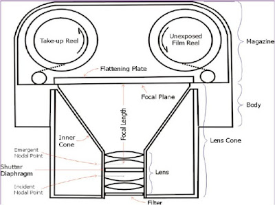
The various types of aerial cameras used in taking photographs is quite different than the ordinary camera as in case of aerial camera. 

aerial camera


Various types of aerial camears:

Single lens camera: A single-lens reflex (SLR) camera is a camera that uses a semi-automatic moving mirror system which permits the photographer to sometimes see exactly what will be captured by the film or digital imaging system, as opposed to pre-SLR cameras where the view through the viewfinder could be significantly different from what was captured on film.

Multi lens camera: The multi-lens camera is a unique piece of technology that follows the principles of lomography for capturing still images. Lomography encourages a light-hearted approach to photography and encompasses over-saturated colors in the images, blurring, and alternative film processing techniques.
Strip Camera:

Panoramic Camera: 
Digital Cameras:
 The use of digital cameras is slowly increasing in popularity, paralleling the popularity of digital cameras in the general public.

The CCD (charged coupled device) is the electronic component on which the light from the lens is focused.
 Digital pictures are made up of tiny "squares", each of a single color, called pixels. Each CCD has a maximum number of pixels that it uses to generate the image.
 Camera specifications will list the Max Resolution and the Minimum Resolution.

Some of the cameras used in aerial photography are:

-Zeiss RMK 15/23(digital camera)

23*23 cms picture format,6 inch focal length
-2fairchild kc-6A
23*23 cms picture format,6 inch focal length
Wild RC-10
 (having different focal  lengths;89,152,210,305 mm)
Hasselblad MK-70
Itek LfC (large format camera )

Aerial triangulation in 3D aerial photogrammetry


Aerial triangulation in 3D aerial photogrammetry is a mathematical process used to determine the position and orientation of each photograph at the moment of exposure. Aerial triangulation in 3D aerial photogrammetry solves for each photo’s exterior orientation parameters, which convey the information necessary to convert image measurements into ground coordinates, as well as determine image points that correspond to points on the ground.

aerial traingulation


- Aerial triangulation in 3D aerial photogrammetry is a critical step related to the project’s quality, and is at the heart of all photogrammetric processes.

- The computed result of Aerial Triangulation in 3D aerial photogrammetry gives the computed EO parameters (X, Y, Z, omega, phi, kappa) which is used to generate the highly accurate stereo model (3D) without any parallax which is further used for DTM generation, Orthophoto creation, Mapping purposes, Application of different projects like urban planning, Utility mapping etc. 

- Aerial Triangulation in photogrammetry is the first step to perform in the Photogrammetric Project. 

- Aerial triangulation has been a complex operation which includes planning the photo flight, establishing ground control points, taking and developing aerial photographs based on preset specifications, performing interior orientation, measuring and transferring all tie, check, and control points appearing on all photographs, and performing a least squares block adjustment.

- This process ultimately provides the exterior orientation parameters for all photographs and the three dimensional coordinates for all measured object points.

- Inner Orientation requires measurement of image coordinates of fiducial marks; this orientation is followed for the images taken with analog camera which is having fiducial marks. 

- The measurement of tie points could be done manually or automatically. 

- The automatic measurement of corresponding points for Relative Orientation is based on the image matching. 

- The measurements of control points are necessary for Absolute Orientation of photogrammetric model. 

- The knowledge about convenient choice of their position is important for good quality of the training process. 


- The automatic identification of control points is more difficult. At present there are two strategy lines in practical use, which can be pursued in digital aerial triangulation in 3D aerial photogrammetry. 

- The first strategy uses semi-automatic methods in which the human operator selects interactively one or several suitable tie-points in an image and gives the approximate location of its homologous points in the other images. Then the image point is transferred automatically by image matching.

- The second strategy, which is pursued here, goes one essential step further and attempts a fully automated procedure for selecting, transferring (matching) and measuring tie-points. 

- In this case not only the selection of tie-points is automatic but the approximations are obtained automatically too. The operator only has to give the initial approximations (block-configuration, forward- and side-overlap) and control the results. 

- The main specifications of aerial traingulation in 3D aerial photogrammetry is the system’s concept are automation and sub pixel accuracy.

What is Photographic Film in aerial photogrammetry


Various types of Films and Lenses are used in aerial photogrammetry. Here we have discussed a verious type of films and lenses used in aerial photogrammetry. Photographic film is a sheet of plastic (polyester, nitrocellulose or cellulose acetate) coated with an emulsion containing light-sensitive silver halide salts (bonded by gelatin) with variable crystal sizes that determine the sensitivity, contrast and resolution of the film.

 Types of film generally used in aerial photography include:

 a.   Panchromatic. This is the same type of film that is used in the average hand-held small camera. It records the amount of light reflected from objects in tones of gray running from white to black. Most aerial photography is taken with panchromatic film.

 b.   Infrared. This is a black-and-white film that is sensitive to infrared waves. It can be used to detect artificial camouflage materials and to take photographs at night if there is a source of infrared radiation.

  Color. This film is the same as that used in the average hand-held camera. It is limited in its use because of the time required to process it and its need for clear, sunny weather.


  d.   Camouflage Detection. This film is a special type that records natural vegetation in a reddish color. When artificial camouflage materials are photographed, they appear bluish or purplish. The name of this film indicates its primary use.

Various Lenses used in aerial photogrammetry:


  A simple lens consists of a piece of optical glass that has been ground so that it has either two spherical surfaces or one spherical surface and one flat surface.

 Its primary function is to gather light rays from object points and bring them to focus at some distance on the opposite side of the lens .

-A lens accomplishes this function through the principle of refraction. 

-Lenses are classified by the curvature of the two optical surfaces.

-A lens is biconvex (or double convex, or just convex) if both surfaces are convex.

 -If both surfaces have the same radius of curvature, the lens is equiconvex. 

-A lens with two concave surfaces is biconcave (or just concave).

-If one of the surfaces is flat, the lens is Plano-convex or Plano-concave depending on the curvature of the other surface. 

-A lens with one convex and one concave side is convex-concave or meniscus. It is this type of lens that is most commonly used in corrective lenses.

LIDAR image of World Trade Center April 2010

New LIDAR images taken in 2010 will reveal extremely fine detail of the9/11 development site. Using Remote-sensing technology to create the maps included aerial photography, laser-based instruments called LIDAR (light detection and ranging), and thermal sensors. Mounted on planes, LIDAR penetrated the heavy smoke rising from the devastated area and captured the first clear images of the scene.
lidar-image-of-wtc


Thermal imaging was used to determine where fires were still smoldering and, over time, the movement of these "hot spots" throughout the area. 

Terrestrial lidar


A new technology is being deployed by U.S. Geological Survey scientists this weekend to map urban flooding caused by Hurricane Isaac.  Called “terrestrial lidar,” or “T-lidar”, this new capability will enable scientists to collect highly detailed information in select population areas in Louisiana, Mississippi, and Alabama where the hurricane had the greatest impact.
3-D Mapping of Isaac Water Levels
The portable instrument allows scientists to quickly generate 3-D maps of buildings, dams, levees and other structures, and can show areas of storm damage as well.  In a four-to-five minute scan, the instrument collects millions of topographic data points in a full 360-degree view to quickly produce highly accurate topographic information and can map areas up to two-thirds of a mile away.

The information gathered from this pilot project will be used by USGS to develop 3-D models of streets and structures, including the levels floodwaters reached, as well as current water levels in the form an interactive 3-D flood inundation map.  The map will help identify where the potential threat of future floodwaters is greatest, and will help determine the extent of wind and flood damages caused by Isaac.

"If a picture paints a thousands words, a T-lidar scan paints several million words to capture the fleeting aftermath of a hurricane's impact," said USGS Director Marcia McNutt. "The ability to rapidly preserve for posterity a quantifiable, three-dimension representation of storm damage is going to open the doors for new flood hazard science."

T-lidar looks sideways from ground level, enabling it to capture vertical details, such as water levels, that airborne lidar cannot.  This enables it to capture the extent of flooding.  The USGS will be using both a tripod mounted and a truck-mounted version.  While the tripod version takes individual scans from multiple locations that later have to be combined to develop its 3-D maps, the truck-mounted version is continuously collecting information that is available almost immediately.

"Using terrestrial lidar in this fashion has the possibility of helping us quickly assess high-water marks, current water levels, and to some degree flood damage, in a very short time," said Athena Clark, director of the USGS Alabama Water Science Center.  "We’re always looking for better, more efficient and cost effective ways of advancing the science and this technology has some great possibilities."

"Lidar" stands for "light detection and ranging."  Where "radar" uses radio waves as a form of measurement, "lidar" uses light.  Terrestrial lidar, sometimes called “terrestrial laser scanning,” uses a sensor that emits laser pulses and measures distance by how long it takes the reflected laser beam to "bounce back" to the instrument. TLS can provide very precise data, to millimeter accuracy, to enable scientists to build high-resolution 3-D models of objects.

"We are collecting storm-tide information that will allow scientists to study the impacts of the storm in three dimensions," said Toby Minear, a research hydrologist at the USGS California Water Science Center, who is participating in the study. "Imagine a 360-degree panoramic photo, but made with laser points where everything you can see has a known elevation and location. These 'point clouds' can be put together to create a full 3-D map of an area containing many millions of data points."
In addition to the use of terrestrial lidar, the USGS is also planning airborne lidar flights to assess the level of coastal change caused by Isaac along the Gulf Coast.  More information on both these studies will be released when they are completed.